Monday, April 22, 2013

Wiring Mitsumi stepper ( M42sp-4np) with arduino

The mitsumi M42sp-4np is a stepper motot available on various devices like scanners, fax, etc.

http://www.scribd.com/doc/24950646/Motor-m42sp-4np-Datasheet


Mine was found on a AVEc scanner, with a SCSI interface. Due to this aging interface and its impossibility to use it on other more modern systems, I decided to take it apart and salvage parts.

AFter some screws, two interesting things are available, the main board and the stepper motor in charge of moving the scanner itself.

The board itself can be used to recover some a voltage regulators, caps, coils, smd components, dip switches and the darlington driver, however is a Surface Mount chip, making it hard to use on Protoboards. In adition, a heatsink is available and some fancy bios. The Imaging chip and the SCSI chips have no documentation so is better to ignore their existence.

For the motor, a set of bands and gears are available, which can be immediately used for mu future 3D printer. Getting back to the motor, it isa unipolar stepper with a 2 2  phase excitation, meaning that both coils are needed to turn the motor, instead of more simple ones, where one coil at a time is required.

General information about steppers can be found here:
http://homepage.cs.uiowa.edu/~jones/step/circuits.html

Details about the pase excitations can be found on
http://www.societyofrobots.com/member_tutorials/node/28
and the used sequence  is presented here...


2-2 Phase Excitation
This mode requires more power, but it also offes more torque than 1-1 Excitation. 2 coils are charged at a time
Step number1a 1b 2a 2b
11001
21010
30110
40101
51001


Details about pinout are not available, however  this link helped me out to figure out the right pinout:
http://ssecganesh.blogspot.mx/2008/05/identifying-leads-of-unipolar-stepper.html

The stepper is a fire wire, and as such is not possible to use the multimeter to find out the coils, however is possible to find out applying voltage on its pins.

Extracting from the mentioned page

  • Five wire motors:Measure the resistance between all pairs of wires. One wire will read about one half the resistance to all other wires when compared to the resistance between other pairs. This wire is the common wire. No wires are joined in this case.
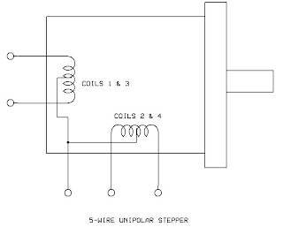
Now, proceed to identify individual coils in order of sequence.
  • Connect the common lead to the positive of your battery or power supply.
  • Connect any one of the other four leads to ground. This will be coil 4.
  • With coil4 still grounded, connect another lead to ground. If the shaft does not move, you have coil2. If the shaft rotates clockwise, you have coil3. If the shaft rotates counter-clockwise, you have coil1.
  • Repeat until you have identified all four coils.
Based on the mentioned tests, thepinout is the following
1 Black         Coil4             A12 Brown       Coil 2            A23 Orange      Coil 3            B14 Yellow      Coil 1            B25 RED           VCC


Finally, a ULN2003APG driver is used to connect the stepper to the arduino,  and feed it with 12 volts.
Used pins are pin 8,9,10,11
Video of the working motor is available here

The used code used to drive the motor is quite simple.


int motorPin1 = 8;
int motorPin2 = 9;
int motorPin3 = 10;
int motorPin4 = 11;
int delayTime = 10;

void setup() {
  Serial.begin(9600);
  pinMode(motorPin1, OUTPUT);//coil1
  pinMode(motorPin2, OUTPUT);//coil1
  pinMode(motorPin3, OUTPUT);//coil2
  pinMode(motorPin4, OUTPUT);//coil2
}

void loop(){
  for(int i = 0 ; i < 100; i++)
    phaseTestFwd();
  for(int i = 0 ; i < 100; i++)
    phaseTestBack();
}

}

//mitsumi servo
void phaseTestFwd() {
  Serial.println("1");
  digitalWrite(motorPin1, HIGH);//1
  digitalWrite(motorPin2, LOW);
  digitalWrite(motorPin3, LOW);
  digitalWrite(motorPin4, HIGH);//2
  delay(delayTime);

  Serial.println("2");
  digitalWrite(motorPin1, HIGH);//2
  digitalWrite(motorPin2, LOW);
  digitalWrite(motorPin3, HIGH);//1
  digitalWrite(motorPin4, LOW);
  delay(delayTime);

  Serial.println("3");
  digitalWrite(motorPin1, LOW);
  digitalWrite(motorPin2, HIGH);//1
  digitalWrite(motorPin3, HIGH);//2
  digitalWrite(motorPin4, LOW);
  delay(delayTime);

  Serial.println("4");
  digitalWrite(motorPin1, LOW);
  digitalWrite(motorPin2, HIGH);//2
  digitalWrite(motorPin3, LOW);
  digitalWrite(motorPin4, HIGH);//1
  delay(delayTime);


}
void phaseTestBack() {
  Serial.println("8");
  digitalWrite(motorPin1, LOW);
  digitalWrite(motorPin2, HIGH);//2
  digitalWrite(motorPin3, LOW);
  digitalWrite(motorPin4, HIGH);//1
  delay(delayTime);

  Serial.println("7");
  digitalWrite(motorPin1, LOW);
  digitalWrite(motorPin2, HIGH);//2
  digitalWrite(motorPin3, HIGH);
  digitalWrite(motorPin4, LOW);//1
  delay(delayTime);

  Serial.println("6");
  digitalWrite(motorPin1, HIGH);
  digitalWrite(motorPin2, LOW);//2
  digitalWrite(motorPin3, HIGH);
  digitalWrite(motorPin4, LOW);//1
  delay(delayTime);

  Serial.println("5");
  digitalWrite(motorPin1, HIGH);
  digitalWrite(motorPin2, LOW);//2
  digitalWrite(motorPin3, LOW);
  digitalWrite(motorPin4, HIGH);//1
  delay(delayTime);

}


Cheers

UB


Tuesday, July 17, 2012

First Impressions with 3DcityDB for PostGIS

Hi.

By some previous work with 3DcityDB and CityGML, and also by an email of a collegue Hugo.L, i was tempted to test both PotsGIS 2.0 and 3DCityDB for PostGIS.

I will skip the installation of Postgres and PostGIS on my MAc and jump straight into the review of the  product.

Impressions:

After following the Tutorial document which required to create a DB using whatever you like and enable it to PostGIS, next steps require additional scripts, however they are created for windows  or at least the
CREATE_DB.bat

which calls

CREATE_DB.SQL

The first one I  tried to UNIXify or macify it :

#/bin/sh                                                                                                                        
echo batchfile that calls CREATE_DB.sql
export PGPORT=5432                                                                                                             
export PGHOST=localhost                                                                                                        
export PGUSER=postgres                                                                                                         
export CITYDB=3dcitydb                                                                                                         
export PGBIN=/usr/local/pgsql/bin                                                                                              
echo  creating the 3D City Database
$PGBIN/psql -d $CITYDB -f CREATE_DB.sql -h $PGHOST -p $PGPORT

however i had no success as I am not hardcore with scripting, 


batchfile that calls CREATE_DB.sql
/psql: No such file or directory/pgsql/bin

however I ran the script by manually like this

$ /usr/local/pgsql/bin/psql -d 3dcitydb -f CREATE_DB.sql -h localhost -p 5432 -U postgres


after which i was prompted for the following

Please enter a valid SRID (e.g., 3068 for DHDN/Soldner Berlin):                28992
Please enter the corresponding SRSName to be used in GML exports (e.g., urn:ogc:def:crs,crs:EPSG::3068,crs:EPSG::5783):                          urn:ogc:def:crs:28992

28992                                    for the Dutch EPSG or SRS number
urn:ogc:def:crs:28992,       well, I just came with that to see what happens

and after endless SQL functions executed, the following errors appeared


CREATE FUNCTION
psql:PL_pgSQL/GEODB_PKG/MATCHING/MERGE.sql:215: ERROR:  invalid byte sequence for encoding "UTF8": 0xe46e64
psql:PL_pgSQL/GEODB_PKG/MATCHING/MERGE.sql:301: ERROR:  invalid byte sequence for encoding "UTF8": 0xe46e64
CREATE FUNCTION
CREATE FUNCTION
CREATE FUNCTION
psql:PL_pgSQL/GEODB_PKG/MATCHING/MERGE.sql:646: ERROR:  invalid byte sequence for encoding "UTF8": 0xe46e64
CREATE FUNCTION
CREATE FUNCTION


I checked my database and is UTF8 encoded so, I checked the sql, and such lines correspond to  extra spaces after the $$ symbol, so maybe as UNIX scripting dislikes spaces i remove them, but no success as that is no unix script.

After some tests with different editors, I tried opening my MERGE.sql with JEdit and after reloading as UTF8 showed a UTF8 ERROR somewhere in line 258 , 159 and 593

    -- building furniture (in rooms) --bei lod r in f ge�ndert

so i removed the offending character and now it ran flawlessly

Future experiences will  follow.

SE ya!


Monday, July 09, 2012

Geoserver ImageMosaic plugin mini troubleshooter

Geoserver Image Mosaic Plugin troubleshooting.

During a recent project, I was challenged to load thousands of images using Geoserver, which is not perfectly suited to this task, due to the high footprint incurred in creating multiple layers and the loading of images and Geoserver itself.

To overcome the situation, the ImageMosaicPlugin offers a nice option to load a folder with images as a single layer where every image should have the following characteristics:

the image
E13B33B.jpg (or TIF or PNG or ...)
the world file
E13B33B.jgw (of TFW or PNW or ...)
and the most important, the projection file
E13B33B.prj

The image file explains by itself, is the raster you want to display.

The world file is a small text file including the size of the pixel in both horizontal and vertical direction, expresed with the first and fourth line. That size is expressed on the same units as the image, which in my case is on decimal degrees.
The last two lines correspond to the center position of pixel in the up left corner


0.00002777777775
0.0
0.0
-2.77777777777778E-05
-104.222208333111
19.4999861110111

And Finally, the PRJ file is the definition of the projection, which I extracted using GDALINFO


GEOGCS["WGS 84", 
  DATUM["World Geodetic System 1984", 
    SPHEROID["WGS 84", 6378137.0, 298.257223563, AUTHORITY["EPSG","7030"]], 
    AUTHORITY["EPSG","6326"]], 
  PRIMEM["Greenwich", 0.0, AUTHORITY["EPSG","8901"]], 
  UNIT["degree", 0.017453292519943295], 
  AXIS["Geodetic longitude", EAST],
  AXIS["Geodetic latitude", NORTH],  
  AUTHORITY["EPSG","4326"]]


Is important to add this last file because otherwise you will receive the following error:


Could not list layers for this store, an error occurred retrieving them: Unable to acquire a reader for this coverage with format: ImageMosaic


So be sure to have them all.

Now that you have all the files in a folder fulfilling this characteristics and requirements, is possible now to use the ImageMosaicPlugin to load that folder, which will automatically create a shapefile containing the spatial index if the images, and which can be further queried using CQL, which i hope I will explain later.

Hope this helps.

Cheers.
UB

UPDATE:


In case u forgot some of the previous steps. the Plugin will create a shapefile named after the directory, so be sure to delete all created files with .shp and alikes, otherwise  it will fail to create the desired layer.


Sunday, October 23, 2011

Layar Update

I received an Email from the Layar Dev Team informing that the new Platform named
Layar Vision     http://www.layar.com/
is out, and  allows to use a recognition image API to create amazing apps.

This nice feature will run on their servers and  will allow you  15000 hits per month without cost but
 the following hits will be charged at some 10 euro cents,
however the next 10000 hits will cost you 1000 Euro monthly, which hopefully will produce  some profit it they manage to sell.

I have never seen somebody selling image recognition services and somehow is a nice approach, however more testing is needed.

However, the thing that interests me  the most is the
JLayar converter tool which this time reaches version 3.0 and includes some nice features like...

http://layar.pbworks.com/w/page/32587974/Release%20History%20-%203D%20Model%20Converter


  • Version 3.0

         What's new: 


    • Overview panel : added "Minimum layar version" field which indicates on which layar client version this 3D model is supported.
    • Materials panel: material names are listed to ease material modification.
    • Materials panel:  material transparency is supported and can be manipulated using the Opacity value. The Opacity value embedded in .obj/.mtl files will be prefilled if it is present. By default, the value is 1.
    • Materials panel: color blending (alpha) is supported. when blending is enabled, it means that color value of this material is blended with the color of any other objects that are rendered behind it.  If it is disabled, it means the objects that are rendered behind it are hidden from view.
    • Materials panel: Added "Shader" with two options - default & nolighting. The "nolighting" option is for people who want to bake lighting effects into textures instead of relying on the standard lighting from the AR view. 
    • "Save for version" option makes it possible to save the same model for different layar version. This is useful when you want to have your models work on various versions of layar clients. You can determine which 3d model should be returned in getPOIs response based on the "version" parameter in getPOIs request. Please NOTE that if you save the model for a specific older version, some features will be stripped from the model. For example, transparent materials might become opaque, and animated textures might be converted to a static version.

          Known issues:
    • Need to throw error messages when there is no material attached an .obj file and there is no material name in .obj/.mtl files.


For me the most interesting feature was the use of material transparency and color blending which will allow me to work on my thesis on advanced visualization techniques. Nevertheless, the Image recognition suite can  allow  some increased accuracy if the API is flexible enough to modify the positioning of the GPS and even replacing the positioning when combining some 3d existing models.
...


Wednesday, June 22, 2011

A long time ago in a country far far away!


It has been a long time since I dont use this blog, so a big gap may be visible to my zero fans!!

The most recent work i been doing on this lands relates to Layar, yes, crappy LAyar!.
Somwhow my very first post were related to extruding Buildings on WorldWind and now, 4 or five years later, I am still working on 3d buildings. Interesting...

During the last two months I've been trying to enable it as a GIS AR client with some limited success. I would mention is a nice idea to have an AR client on Android, however, as they said on some recent presentation, they dont know how to make money from it and they still need a rocking application to prove it!

As a GIS enthusiast and a Geomatics student, I strongly believe on the possibilities created by such merge. Of course my recent work/research/failures on this task has proven many things:
Layar still has potential
Layar can be GIS enabled
Developers at LAYAR are really wasting their time upgrading it with silly features, instead of allowing to display wireframe, transparencies, better sensor calibration, etc.
Layars needs more documentation.

In short, the project looks promising but they need more crunching power on their developers.

Cheers!


Thursday, July 13, 2006

Generating 3D buildings inside WorldWind like GoogleEarth do


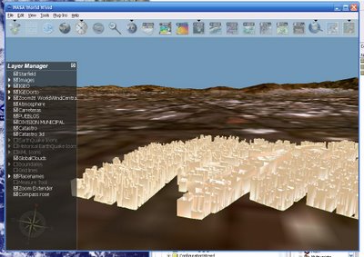
I have been working with DirectX adding building strutures inside WorldWind.
Data is extracted directly from a shapefile. There is one field containting the number of levels for each structure.
The shapefile contains polygons.

The base poygon is placed at ground level taking its altitude from the Terrain and the structure height from the number of levels .

The result is a life like picture of Mexico DF, at least part of Miguel Hidalgo.


As you can see, there are no ceilings, but im working on it.
This project is meant to be used as a WFS client for Urban Areas, but needs lot of work!!